Shader Graph - Biome Textures distribution + blend

Hello,

I have been trying for some time now to generate a procedural terrain with multiple biomes based on height, temperature and moisture. I am new in all of this, so this is my first game I am building. I know this is a complex thing to do, and I should have started with something less complicated, but I also like to deep dive in anything, not keeping back on anything just because it’s complex :slight_smile: So yeah, this is my first post here aswell.

Now, to the point. Each biome has an index; e.g. 1 or 2 or 3 or 4 or 5 based on the combination of the height, temperature and moisture.
I am keeping these information in each vertex in the uv2 channel, in a Vector2 (biomeIndex, 0).


This is an example of the map I have with biomes distribution. This is just a test and by far not a realistic one, but still works for now, so don’t judge me too harsh for the distribution :slight_smile:

The problem I have is that when each biome texture is being drawn by Shader Graph, it is also drawing the biomes textures that are before the one the current biome is being drawn. Check picture bellow to see what I mean:
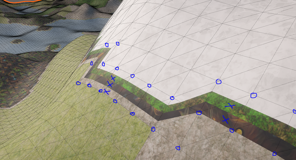

As you can see, here are the extra textures that I want to be removed, the ones with x. The circles are vertexes examples in which the uvs2 info is kept. All mesh vertices have these informations, not only the ones circled.

And this is the Shader Graph I am using:
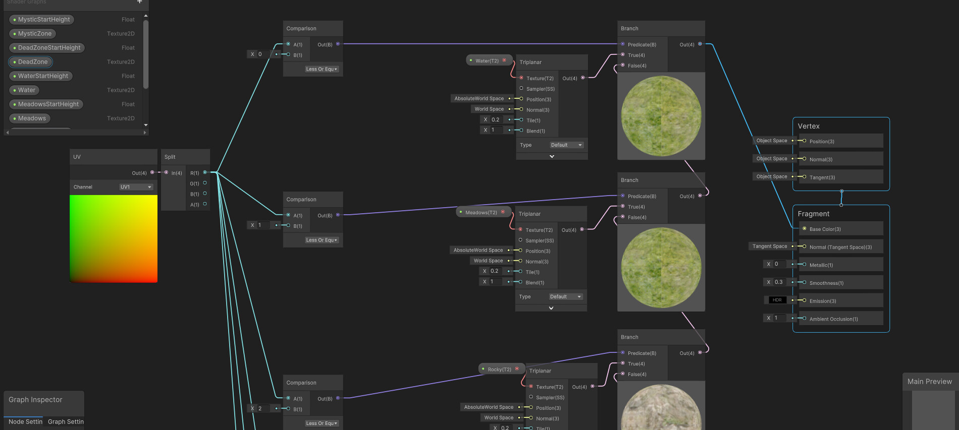

What am I doing wrong? I have tried the comparison for Equal, or Grater than, etc, all ending up in a worse situation in which textures were overlapping. Also, note that even in this case, some texture are overlapping, creating this effect:

Could someone please point me into the right direction? Also, an advice regarding the blending of the biomes between eachother? Would be awesome! I know I can use Lerp and Inverse Lerp for these but from what I’ve tried so far just makes the blending way too large, not just a little where biomes meet.

Thank you for reading the long post!

Hi, I think the range of UV is between 0.0 and 1.0 (should be float32) when it’s not outside border.

You can try mapping them to integers (int/uint) then do the comparison.

Actually they can be any values you need. As far as I know the values between 0.0 and 1.0 are used to play with lightning representing like a percent of the distance or something like that.

If values would be between 0.0 and 1.0 it will not be able to render the textures as you can see in the pictures (e.g. the biome 2 or 3 is being rendered and it is compared with ‘less or equal’ than 2 or 3).

Thanks a lot for the input, but I think the solution might be somewhere else.

Thanks for the reply, very much appreciated! :smile:

I find it a bit hard to understand what you are saying, as I said, this is my first time creating a game, and just found out about Shader Graph :slight_smile: even so, I can intuit what you are talking about, but this will take me a lot of time to figure out alone.

I thought I was doing something wrong the way I’ve built the Shader Graph, the way I made the connections. Does this mean that there is no way to fix it just by rearranging or using another strategy on how to form the nodes of the graph?

Also, maybe there is a way to replace the linearity between the vertexes that form the border with a blend/gradient between the two biomes? Always thinking that maybe, maybe there is a simpler solution hehe :roll_eyes:

In my understanding, the mesh only stores data per vertex. A shader usually has a vertex stage and fragment (pixel) stage.

The vertex shader runs for every vertices. UVs are stored per vertex, so the shader will (linearly) interpolate them and pass the inerpolated UV to the pixel shader stage. That’s why GPU knows which texel it (the pixel shader) needs to sample.

When there’re some adjacent vertices that the range of their UV is different (like 2-4), some pixels will receive interpolated values between the range (2-4, like 3.1) because of the interpolation.

Thanks for the info, this really helped add some more on my starting knowledge cache, which is really valuable, and it also makes sense.

Now I will have to figure out how to implement this into my mesh data and how to also get and use this data in Shader Graph. I could not understand exactly how to do this or how to store and what exactly needs to be stored.

I do not need to be spoon feed, it’s not a way of learning for the long term, but I cannot find any documentation in which it tells how and what data to store so you can manipulate the fragment texture rendering and also how to do it in Shader Graph.

I am still thinking that maybe it would be a better idea to replace the interpolation in the fragment with some Lerp between the textures of the two neighbors biomes, although the line between them would be maybe too small, which means that a sort of control on the ‘length’ of the blended textures would need to be in place.

Maybe it is just not the best approach on how I’ve put the nodes together?

I keep thinking that maybe if I would approach the blending/lerping/smoothness solution it will just overwrite the interpolation problem aswell. Am I correct?

Or, to put it differently, how can I form the Shader Graph nodes so I can have textures for each biome, and some small blending textures between the biomes borders? (I can have the biomeIndex number into an uv channel, or in vertexColor as one of the R or G or B value. important is that I have the index of the biome for each vertex).

Bumpy :slight_smile: