I’ve been trying to get this working using multiple different solutions and coming up short every time. For context, I am very inexperienced with the shader graph, but have put a few things together before. Here’s everything I’ve tried so far.
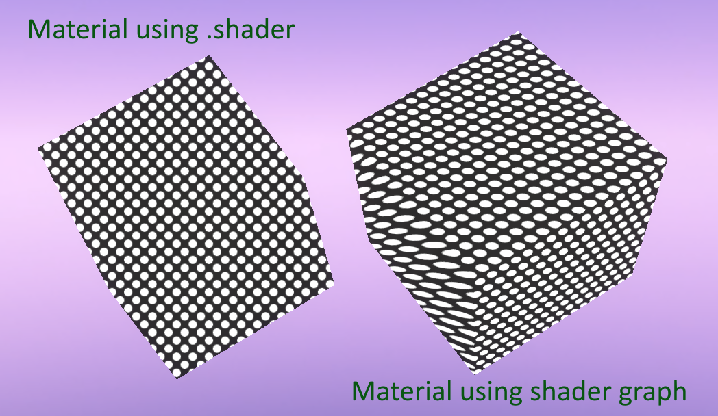
I was able to get this code into my project, and in testing, this code is what I would like to replicate in the shader graph. Here’s what it looks like in my project:
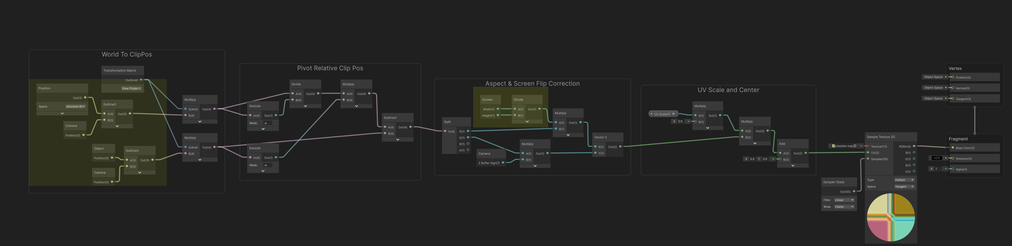
Using another forum post I found that tried to replicate the function of UnityObjectToClipPos in the shader graph (although not exactly, as there aren’t any input parameters), I had a crack at trying to recreate the shader using the shader graph. Unfortunately, I couldn’t get it to work after trying several node input/ouput configurations.
To be clear, I don’t specifically need this implemented using purely nodes or anything. I just need an RGBA output that has the texture sampled with the correct UVs in such a way that the texture would look the same as it does in the shader code. I’d like to use the shader graph to manipulate the output further, so I need some way of getting this into the shader graph. Another note, this material is meant to be unlit and without shadows, and Opaque with alpha clipping. I’m trying to do something stylised and want it to be fully unlit, if that’s relevant here at all, which I don’t think it is…?
Problem with this one was that the texture would scroll like crazy as soon as the camera would start moving. I would probably be fine with it if it wasn’t perceptually perfectly stationary, but I couldn’t figure out how to get it to not look like it was scrolling using just offset.
You’re absolutely magic, man. I’d spent like all day trying and this was the best I had, and it isn’t exactly what I wanted.
Your shader’s working perfectly! I seriously appreciate the time you took to help me out. Shaders are absolutely something I want to get better at, so I really appreciate the annotations to help break down what’s happening throughout the graph.
Oh, sorry to bump this again, but there is one problem I was hoping I could get some input on. This has nothing to do with the shader graph adaptation, rather it’s a problem present even in the original shader.
It seems like the shader is having some trouble dealing with certain angles and/or distances, and I’m not really sure what the common thread might be.
And it seems to be happening on the original shader too.
I would just try to ignore this issue, but considering how often it seems to happen and how common the angles that it happens are, I don’t think I’d be able to just work around it.
My first thoughts are that it might be related to when distance is below 1 or something, but really I’m just not sure where to start. I was hoping maybe you’d have an idea what might be causing this and where to begin with preventing it from happening, if it wouldn’t majorly complicate things further than they are already.
For a character that’s usually at the feet. That’s where the screen UV is “rotating” around.
I’ve solved this by having a script that tracked the world position of a position attached to a skeletal mesh bone and set that position on the material every frame. I then have the material use that position instead of the object’s pivot if it’s set. That mostly fixes the worst issues.
The issue you’re seeing on the box though, that’s effectively the same issue, and is unavoidable at a certain point. Because the screen space UVs have to be centered on something, your options are the middle of the screen, in which case they don’t stick to objects at all and can’t really be scaled by distance easily. Or they’re some other arbitrary position like a pivot or some other world position in which case when that point gets far off screen things get wonky for what remains on screen.
Ahhh okay I getcha, I can visualise exactly what’s happening here now. When I’m back at my computer I’ll get to adding a Y offset parameter so I can declare the “origin” a little higher than at the feet like on that model. Thanks for the help again!
That “scale change with screen position” was the explicit goal the OP was trying to achieve. What you posted is how to get screen space UV with aspect correction, which wasn’t what this thread was attempting to solve.
The main difference from URP is that HDRP uses camera relative rendering. When multiplying positions by UNITY_MATRIX_VP, you cannot just use absolute world positions. You need to subtract _WorldSpaceCameraPos first so the position is camera relative, because that is how HDRP’s view and projection matrices work. Make sure you do this for both the surface position and any pivot point you are projecting from.
For aspect ratio scaling, do not use the camera node, use the actual screen width and height to keep the projection consistent.