Rendering Object Thickness/Volume with Two-Pass Shader

I’m trying to implement this method for rendering thick glass into Unity:

http://prideout.net/blog/?p=51

( Note that I do not want Light Absorption or Fresnel in my shader! I’m just trying to do depth for now. )

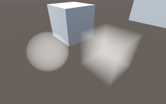
My idea was to add a secondary camera to the scene which is parented to the main camera and renders to a RenderTexture using a shader like the one described in the article. I would exclude the glass object layer from the main camera and include only the glass layer in the secondary camera. So the RenderTexture would look something like this:

Then I would just overlay the RenderTexture result on top of the main camera view with additive blending and color it if I’d like.

The issue I’m having is with writing the shader. I don’t really know what I’m doing when it comes to transforming my vert positions with the matrices, this is what I’ve cobbled together from other people’s code. Here is the best I’ve got so far:

Shader Code

]

Shader "Thickness"
{
    Properties
    {
    }
 
    SubShader
    {
        Tags{ "RenderType" = "Opaque" }
        //LOD 200

        Pass
        {
            Lighting Off
            Fog{ Mode Off }

            CGPROGRAM
            #pragma vertex vert
            #pragma fragment frag
            #pragma fragmentoption ARB_precision_hint_fastest

            struct a2v
            {
                float4 vertex : POSITION;
                fixed4 color : COLOR;
            };

            struct v2f
            {
                float4 pos : SV_POSITION;
                half dist : TEXCOORD0;
            };

            v2f vert(a2v v)
            {
                v2f o;
                o.pos = mul(UNITY_MATRIX_MVP, v.vertex);
                float4 temp = mul(UNITY_MATRIX_IT_MV, v.vertex);
                o.dist = temp.z;
                return o;
            }

            fixed4 frag(v2f i) : COLOR
            {             
                float depth = i.dist;
                return half4(depth, depth, depth, 1);
            }
            ENDCG
        }

        Pass
        {
            //BlendOp Sub
            //Blend One One
            Lighting Off
            Fog{ Mode Off }
            Cull Front
            ZTest Greater /* This was needed to render the back faces on top of the front faces */

            CGPROGRAM
            #pragma vertex vert
            #pragma fragment frag
            #pragma fragmentoption ARB_precision_hint_fastest

            struct a2v
            {
                float4 vertex : POSITION;
                fixed4 color : COLOR;
            };

            struct v2f
            {
                float4 pos : SV_POSITION;
                half dist : TEXCOORD0;
            };

            v2f vert(a2v v)
            {
                v2f o;
                o.pos = mul(UNITY_MATRIX_MVP, v.vertex);
                float4 temp = mul(UNITY_MATRIX_IT_MV, v.vertex);
                o.dist = temp.z;
                return o;
            }

            fixed4 frag(v2f i) : COLOR
            {
                float depth = 1 - i.dist;
                return half4(depth, depth, depth, 1);
            }
            ENDCG
        }
    }
 
    FallBack Off
}

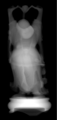
What I have here is my attempt at a 2-pass shader. First a normal Back face culled pass where the pixels are colored by depth. Then the 2nd pass the Front faces are Culled and the depth reversed. Then you can see I tried to change the blending mode to have the 2nd pass’s dark pixels SUBTRACT from the lightness of the first pass’s pixels. I was unsuccessful in figuring out how to do this.

Basically I want the shader to render the front faces colored according to the depth. The closer to the camera the whiter the pixels should be. I also want the depth to be scaled according to the object’s boundaries so that the furthest back pixel is pure black and the closest is pure white, I don’t know how to do this. I basically want the depth not to be dependent on the camera proximity.

The second pass should work the same but with front faces culled and the depth inversed so black is closer and white is further away. Then I want this 2nd pass to blend with the first pass in such a way that the white pixels don’t change the destination pixel color but the darker pixels should darken the pixel colors of the first pass.

I’m trying to do exactly what the shader in the article I linked does. So can anyone help me figure out how to pull this together?

Thanks in advance!

Instead of this

Tags{"RenderType"="Opaque"}

try this:

Tags { "Queue" = "Transparent" }

Instead of this

Lighting Off

try this:

Lighting Off
Blend One One

as described in the shader writing manual, blending section.

Instead of this

float4 temp = mul(UNITY_MATRIX_IT_MV, v.vertex);
o.dist = temp.z;

try this:

COMPUTE_EYEDEPTH(o.dist);

Instead of this

float depth = 1 - i.dist;

try this:

float depth = -i.dist;

although it might be more optimal, or at least better practice, to do the negation in the vertex program.

Tried this. The first pass ends up looking better except that the shading is still affected by the camera distance AND angle from the object.

Problem with the 2nd pass though, it seems to just render solid black:

Pass
            {
                Lighting Off
                Fog{ Mode Off }
                Cull Front

                CGPROGRAM
                #pragma vertex vert
                #pragma fragment frag
                #pragma fragmentoption ARB_precision_hint_fastest
                #include "UnityCG.cginc"

                struct a2v
                {
                    float4 vertex : POSITION;
                    fixed4 color : COLOR;
                };

                struct v2f
                {
                    float4 pos : SV_POSITION;
                    half dist : TEXCOORD0;
                };

                v2f vert(a2v v)
                {
                    v2f o;
                    o.pos = mul(UNITY_MATRIX_MVP, v.vertex);

                    COMPUTE_EYEDEPTH(o.dist);
                    return o;
                }

                fixed4 frag(v2f i) : COLOR
                {
                    float depth = -i.dist;
                    return half4(depth, depth, depth, 1);
                }
                ENDCG
            }

I think the camera distance thing can be fixed by making the depth values linear? I don’t know how to do this though.

you’ll need Blend One One on the second pass if you want the additive effect.

for the linear depth values, you can try passing the depth to LinearEyeDepth (if you want to see what the macros do, download the built in shaders zip from unity for your version, and look CGIncludes\UnityCG.cginc for LinearEyeDepth.)

However, if you read the built in shader code, it is common to compare the result of COMPUTE_EYEDEPTH from a vertex program and sent to the frag program with a LinearEyeDepth from a depth texture, so I suspect COMPUTE_EYEDEPTH is already linear, and that is what I do in my shaders (I don’t pass the value of COMPUTE_EYEDEPTH into LinearEyeDepth, I just assume it is already linear.)

If it’s true that COMPUTE_EYEDEPTH makes the result linear then why does my camera distance still affect the shader?

Here’s what the result is, showing just the first pass as an example:

If I understand your gif correctly, and you are moving the camera closer and farther from the geometry rendered, then I would expect the eye depth value to change, as it reflects the distance from the vertex to the camera in view space. So, if you look at only one pass while you move the camera, it will change.

However, if you succeed with both passes, the result should be the difference between the back and front face depths, and then it would not appear to be different when you move the camera

I get the same result as the GIF even if I enable the second pass. Here’s what my shader looks like right now:

Shader

Shader "Thickness"
{
    Properties
    {
    }

    SubShader
    {
        Tags{ "Queue" = "Transparent" }

        Pass
        {
            Lighting Off
            Fog{ Mode Off }

            CGPROGRAM
            #pragma vertex vert
            #pragma fragment frag
            #pragma fragmentoption ARB_precision_hint_fastest
            #include "UnityCG.cginc"

            struct a2v
            {
                float4 vertex : POSITION;
                fixed4 color : COLOR;
            };

            struct v2f
            {
                float4 pos : SV_POSITION;
                half dist : TEXCOORD0;
            };

            v2f vert(a2v v)
            {
                v2f o;
                o.pos = mul(UNITY_MATRIX_MVP, v.vertex);

                COMPUTE_EYEDEPTH(o.dist);

                return o;
            }

            fixed4 frag(v2f i) : COLOR
            {
                float depth = i.dist;
                return half4(depth, depth, depth, 1);
            }
                ENDCG
        }

        Pass
            {
                Lighting Off
                Fog{ Mode Off }
                Cull Front
                Blend One One
                ZTest Always

                CGPROGRAM
#pragma vertex vert
#pragma fragment frag
#pragma fragmentoption ARB_precision_hint_fastest
#include "UnityCG.cginc"

                struct a2v
                {
                    float4 vertex : POSITION;
                    fixed4 color : COLOR;
                };

                struct v2f
                {
                    float4 pos : SV_POSITION;
                    half dist : TEXCOORD0;
                };

                v2f vert(a2v v)
                {
                    v2f o;
                    o.pos = mul(UNITY_MATRIX_MVP, v.vertex);

                    COMPUTE_EYEDEPTH(o.dist);

                    return o;
                }

                fixed4 frag(v2f i) : COLOR
                {
                    float depth = -i.dist;
                    return half4(depth, depth, depth, 1);
                }
                    ENDCG
            }
    }

    FallBack Off
}

what’s your rendertexture format? You’ll need a floating point version for this technique, as the author described in the page you linked. RenderTextureFormat.RHalf is probably optimal, or RFloat, either way just render to red

I’m not even using a rendertexture at this point. It’s just the shader applied to a normal sphere primitive. The material is just the shader.

oh ok, well negative colors won’t work without a floating point render target:

I’m not sure if this is sufficient, but you could try turning on HDR on your cameras, as a quick test, and see if that floating point buffer is going to work with this technique. The intent of the author on the page you linked though was to use a rendertexture format like RHalf or RFloat

I turned HDR on with both cameras, separated the sphere object to its own display layer, rendered the second camera to a RFloat render texture, and here was the result:

Same problem as before except now it’s red instead of white. When I move the camera closer the center of the sphere becomes more transparent like in the GIF which is the opposite of what I would expect. I would expect the center to be more opaque.

The inspector won’t be able to draw the RFloat or RHalf depth difference texture in the colors you expect. You have to decode it with an image effect, as in the blog post. Here is screen of a demo project I put together, note the camera that renders to the RHalf texture clears solid color to black. Also, once I had things setup correctly, I didn’t see any red in the inspector for the RHalf texture:

In the project view of the screen above, you can see a few assets you can use to get these effects. Here is the image effect that goes on your main camera:

using UnityEngine;
using System.Collections;
[ExecuteInEditMode]
public class ThickGlassImageEffect : MonoBehaviour {
    public RenderTexture thicknessRenderTexture;
    public Material material;
    void Awake () { material.SetTexture("_ThicknessTex", thicknessRenderTexture); }
   
    // Postprocess the image
    void OnRenderImage (RenderTexture source, RenderTexture destination) { Graphics.Blit (source, destination, material); }
}

here is the shader the image effect uses:
ThickGlassImageEffect.shader

Shader “ThickGlassImageEffect”
{
Properties
{
_ThicknessTex(“Thickness Texture”, 2D) = “white” {}
_Color(“Color”, Color) = (1, 1, 1, 1)
_Sigma(“Sigma”, Float) = 1.0
}

SubShader
{
// No culling or depth
Cull Off ZWrite Off ZTest Always

Pass
{
CGPROGRAM
#pragma vertex vert
#pragma fragment frag

#include “UnityCG.cginc”

struct appdata
{
float4 vertex : POSITION;
float2 uv : TEXCOORD0;
};

struct v2f
{
float2 uv : TEXCOORD0;
float4 vertex : SV_POSITION;
};

v2f vert (appdata v)
{
v2f o;
o.vertex = mul(UNITY_MATRIX_MVP, v.vertex);
o.uv = v.uv;

// see Unity - Manual: Writing shaders for different graphics APIs
#if UNITY_UV_STARTS_AT_TOP
o.uv.y = 1 - o.uv.y;
#endif

return o;
}

sampler2D _ThicknessTex;
fixed3 _Color;
float _Sigma;

fixed4 frag (v2f i) : SV_Target
{
// adapted from prideout
float thickness = abs(tex2D(_ThicknessTex, i.uv).r);
if (thickness <= 0.0)
{
discard;
}

float intensity = exp(-_Sigma * thickness);
fixed4 col = fixed4(intensity * _Color, 1);

return col;
}
ENDCG
}
}
}

I’m gonna say to go ahead and read the paper on Colin Barre-Brisebois - GDC 2011 - Approximating Translucency for a Fast, Cheap and Convincing Subsurface-Scattering Look | PPT.

This is a different approach, but gets you a nice thickness approximation - and its pretty cheap too as it’s just a texture map.

I will try this ASAP. Although I noticed that your Game view is showing the same problem with the shader as my shader where the thicker parts of the mesh are being rendered as darker and the thinner parts are lighter. Given the way the passes are written its expected that the opposite would be true?

I read this before while looking for a depth rendering technique but it won’t work for my use case because this technique requires that you have pre-baked local thickness maps. I can’t do this because my shader is going to be applied to dynamic meshes which change shape at runtime.

Yes, I was going to recommend this too. I’ve been wanting to see this in Unity.

Yes! It is inverted after you use the sigma step. If you just render the thickness in the image effect shader, the thicker parts are lighter, similar to the blog post.

After starting over from scratch in a new project I managed to get it to work!

Some notes:

  • HDR was NOT required on either camera.
  • For some reason disabling antialiasing in project quality settings causes the composited main camera view to not render correctly. It just shows the rendertexture and doesnt show the skybox or any objects in its culling layers.
  • To get the desired effect that I wanted (depth rendered to look like gas or a liquid volume) in the ThickGlassImageEffect shader I changed return col; to return 1 - col; to invert the output colors. And then I changed the ThickGlassImageEffect to use ‘Blend OneMinusDstColor One’ (Soft Additive blending).

And here’s the result!:

Exactly what I was trying to do! Thanks for all the help! I didn’t realize how much I was not picking up on from the thick glass technique implementation.

3 Likes

Sorry for replying to old topic,
But you can also use VFACE to get object thickness directly in one pass just using the same technique as in this link
2455117--168712--Screenshot_4.png

1 Like

@Reanimate_L Can you explain how to do this?