How best to make a 4851 color-changing tile grid floor in a 3D scene (current approach too slow)

Hello I have a large grid (think like a checkboard) and each of the tiles change color based on how long they have been “stood on”.

My current approach:

  • parent GameObject

  • procedurally create 4851 child tiles (plane primitives)

  • I have a “GridController” MonoBehaviour that samples players in the scene to get their x,z location (on the grid)

  • I then update all of the tiles’ colors based on how long they have been “stood on”

  • They are all the same material and color, I change the alpha value (transparency) based on how long a tile has been stood on

Issues:

  • With no players standing on the tiles, just the grid “existing”, the FPS is very low and it barely runs

  • This means no players so no “updates” are occurring

  • It seems like the Editor cannot really support the pure number of 4851 GameObjects?

  • Could it be that they all have their own specific “color”? (same material, but different color due to alpha value?)

Is there a more efficient way to make a color changing grid other than making each tile its own GameObject? I just want to change the alpha value of a color.

Firstly, have an ObjectPool for those GameObjects, don’t create them with Instantiate.

Secondly, enable Occlusion Culling on your camera.

There’s two ways I can think of to go about this, first, disable the tiles that aren’t currently rendered so that unity doesn’t have to manage them.
The other way is to completely change your approach, have a mesh with a Material on and ‘paint’ the pixels that you want to change based on where the player is stood. I don’t know much about this to be honest but I imagine it’s possible.

Thank you for your response.

  1. It appears ObjectPooling helps with the initial creation of GameObjects, but doesn’t really help after that. I do not believe this will help with the GameObjects “existing”

  2. Why would Occlusion Culling help? I usually look at the entire grid (so it is always being rendered)

  3. Disabling tiles will be helpful, but eventually the entire grid will be active and I am back at the same problem so it is not a real “solution”

  4. Interesting, how can you “paint” specific areas of a Mesh in Unity? Maybe this could be a solution.

Does anyone know if 1 GameObject with 4851 meshes components would be performant? Or is that many components on a single GameObject also an issue?

Make sure you use the profiler to find out what exactly is causing your project to run slow.

Edit: by the way. if you want to go the procedural mesh solution, a vertex-alpha shader would probably be useful. You could create one big mesh for your entire map and then iterate over the vertices and adjust the alpha there. That way you have one mesh, one material. No material instancing.

You could consider using a single texture on a quad instead. Stretch it so one Texel represents a tile. Then just modify the colors of the texture as you like and apply them (you should have a color array which gets modified and apply this to the mesh).

If this does not work, you could have a single mesh consisting of “quads” at your tiles positions. And set their vertex color.

Note: If your tiles refer to Unity’s 2d system, I have never worked with that, so I cannot tell about the implications.

In general having thousands of GameObjects is rarely a good approach. Especially when they represent some uniform things.

Thank you for your response. This is not regarding Unity’s 2D system. I have a good amount of familiarity with procedural mesh generation but I am having trouble following.

  1. “You could consider using a single texture on a quad instead. Stretch it so one Texel represents a tile. Then just modify the colors of the texture as you like and apply them (you should have a color array which gets modified and apply this to the mesh).”

I believe I am misunderstanding. A single texture on a “quad” (plane?). But if there is many different colors how can a single texture serve that many tiles?

How can one “stretch” a Texel to represent a tile?

  1. “If this does not work, you could have a single mesh consisting of “quads” at your tiles positions. And set their vertex color.”

Sorry what do you mean by “quads” in this mesh? Would those be sub meshes, or just different vertices not connected to each other?
Each tile would be 2 triangles. But each tile shares vertices with other tiles. How can I affect just the color of a single “tile”?

When you “stretch” the texture so a texel of it covers one of your tiles. For example your grid seems to be around 70 x 70 cells. When one cell is one unit in side length you would have one point of your large quad at (0,0,0), one at (70,0,0), one at (0,0,70) and the last at (70,0,70). Then you apply a 128 x128 texture to it (textures must be power of 2) but you use only 70 texels in each direction by modifying the uv’s accordingly. If you do this one texel of the texture should cover one tile.

When your tile is one unit in length your first quad would consist of 4 points (0,0,0), (1,0,0), (0,0,1) and (1,0,1). Second quad could be (1,0,0), (2,0,0), (1,0,1), (2,0,1). And so on. You could apply a certain vertex color to each of your quads (to each of the 4 vertices of each quad).

You are not forced to share vertices. Simply give every corner of your quad a unique vertex at the same position, but independant value with it’s own uv’s and/or vertex color. So just generate the quads according to your tiles and color them. So the whole grid is a single mesh and much faster and more performant to draw than an individual gameobject for every cell.

Thank you again, I believe your second approach makes sense to me. I am not familiar with the concept of “Texels”.

“When your tile is one unit in length your first quad would consist of 4 points (0,0,0), (1,0,0), (0,0,1) and (1,0,1). Second quad could be (1,0,0), (2,0,0), (1,0,1), (2,0,1). And so on. You could apply a certain vertex color to each of your quads (to each of the 4 vertices of each quad).”

I am familiar with a mesh being: an array of vertices, an array of triangles (using the index of the vertices).

  1. So in your suggestion there would be many vertices (up to 4) that are in fact in the same location?

  2. What would be the most performant way to associate a color to a quad? (2 triangles)? I assume a different material per quad would be non-performant.

While a pixel is an element of a picture, a texel is just an element of a texture. So nothing scary ;).

That’s it. It’s totally up to you where those vertices are. They can be connected, or not. They can be shared, or not. If you create the mesh prcodeurally yourself, you are it’s “master” and it has to obey to your will. So go wild and create the mesh you need for your purpose.

All vertices which are not along the outside or the corners would be shared by 4 quads and 2 triangles in each quad. IF you would share them. Just create a new vertex for every quad (triangles of a quad can share them since you want to color them quad wise). And index them properly in your triangle list and you are done. It’s even easier to understand when you not share vertices IMO.

Have an array of Color32 with the same length/amount like you have vertices. When you always create the 4 vertices of a quad together you can also set their corresponding colors together. If the grid is regular the position of an element (where it’s vertices start) can be easily calculated. Then set the color of 4 elements and you are done. I suggest to just try this out on a small grid (like 2x2) first. When something has changed apply the color array to the mesh to “upload” it to the gpu and in the next frame the colors have changed accordingly. Just don’t create a new color array or “download” it by retrieving it from the mesh as this is slow. Your array is the “working copy” and is assigned to the mesh once changed.

A different material would require a submesh. This is not what you want. This is limited to a “handfull” anyway and wont support 5k different colors. Just go the vertex color route. It’s the easiest and most performant I can think of.

Just don’t forget to use a shader which supports vertex colors.
The term when you don’t share vertices for a search engine is “faceted mesh”. It’s often used by low poly style games since the color, lights and so on are not longer interpolated between triangles. So you can better see triangles and their “lighting”.

Again, really appreciate this, it is phenomenally helpful, I am just about ready to implement.
I understand now the quads and triangles and I can just change my references to the GameObjects to references of these quads. I will make structs that contain the indices of the vertexes used by the 2 triangles in order to easily reference them. I can store those structs in the same multi-dimensional array I stored references to GameObjects, so easy enough to switch implementation. (Instead of creating a GameObject at a certain position I will create structs that contain indices of the vertex array that reference the same position)

I am still a bit confused about the coloring. Each of my tiles are the same color, but with a different alpha value. The way I have updated the GameObjects is by setting the material color to a new color that has the calculated alpha value.

  1. “When you always create the 4 vertices of a quad together you can also set their corresponding colors together.”

So in total I would have:

  • array of vertices
  • array of triangles
  • array of vertices colors (Color32) (same size as array of vertices)

So in this case I would calculate the color value for that tile, then update the associated indices in the Color32 array.

Would all I need to do is “apply” it to the mesh? How does one “apply” a color to a mesh? I have only programmatically created meshes that already had an overall material/color applied to it rather than individual vertices.

  1. “Just don’t forget to use a shader which supports vertex colors.”

How is this applied programmatically? What is the right “shader” to choose? (is shader a type of material or…?)

  1. “The term when you don’t share vertices for a search engine is “faceted mesh”. It’s often used by low poly style games since the color, lights and so on are not longer interpolated between triangles.”

Does this mean that the colors won’t be affected by lighting? and it would be a “flat” color? Or is there still somehow a “material” involved?

I think you want something like this → vertex colors

I just installed unity again last week when they released entities 0.50…can see if I find the source and post… will take 2 days as no access to computer before

When your grid is “static” and does not change, those are just needed when you initially create the mesh. They can be freed afterwards. You just would need an array for the colors since you change them frequently.

Right.

mesh.colors32 = yourcolorarray;

Look in the documentation of the mesh class for examples and other uesfull methods. Note that you don’t apply a single color but your color array which has an entry for every vertex in the mesh.

You apply this in advancce (ie in the editor) to your mesh. It is only done once since the shader stays the same. Shader is not a “type” of material but a “part” of it (together with settings and recources like textures etc).

This depends entirely on your shader. The shader takes the mesh as input and calculates how it shall look. There is a new shader graph in Unity where you can design shaders with nodes but it’s only for URP or HDRP pipeline. When you use the alpha you also need a shader which supports transparency (additionally to vertex color). Look at which shaders unity offers out of the box.

If you have difficulties understanding the mesh concept in Unity I suggest to watch some proc gen tutorials on youtube or read CatlikeCoding’s mesh generation tutorials.

I would also go for a procedural mesh approach. I once made a computercraft clone in Unity (though it was never really finished ^^). I have MoonSharp up and running (single thread, so would even work for WebGL builds and full lua coroutine support and infinite loop handling).

I made a text renderer screen that consists of many quads, one for each character. I used an old DOS font texture. I made a simple shader that uses the vertex color as foreground color and a second uv channel as background color. The alpha channel of the background color is even used for an automatic blinking behaviour. This is used for the cursor quad which is just an additional quad at the end of the vertices list. When I want to write a character to the screen, all I have to do is set the 4 uv coordinates of the 4 corners of the corresponding quad to the character I’m interested in. This update is extremely fast. So in the end I have a single mesh with a single material that can render the whole screen in one drawcall and it looks like this.
7985676--1025778--CCScreen.gif

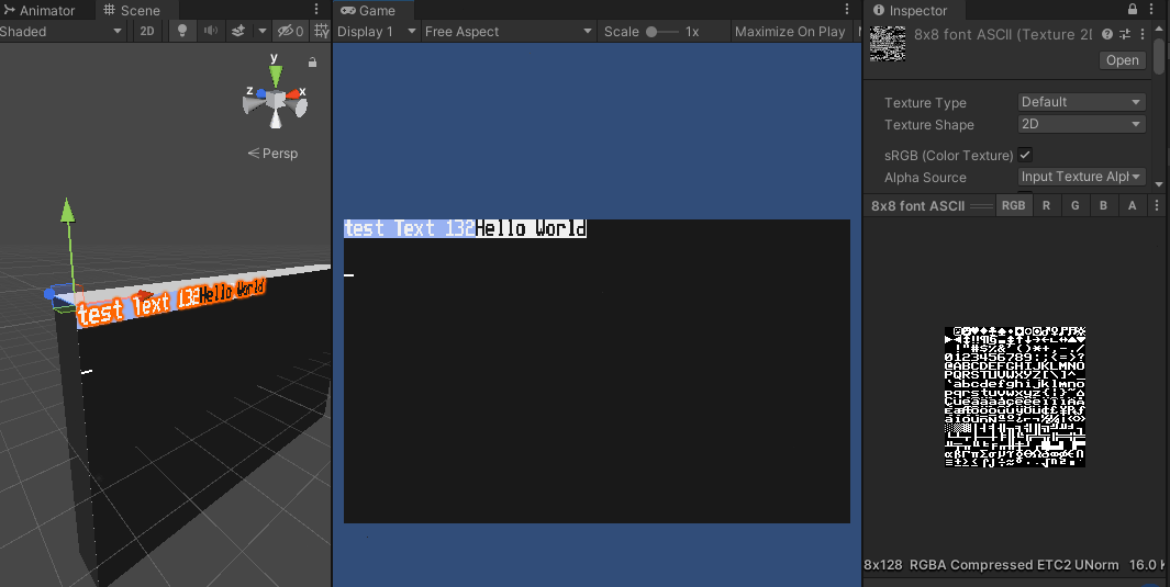
This is actually a lua program controlling the screen and it actually uses the same event system as computercraft. So in the end I want usual CC programs to be compatible. So maybe, one day, it will become a full turtle simulator :slight_smile: Though I don’t have much time recently so it’s currently just another project on hold :smile:

lua code

If someones interested in it, this is the actual lua code running on the lua runtime.

local function test()
    error("111",222)
    coroutine.yield("test", 2)
end

   print("test started")
   term.clear()
   term.setCursorPos(1,1)
   term.setBackgroundColor(8)
   term.write("test Text 132")
   term.setBackgroundColor(128*256)
   local co = coroutine.create(test)
   local res = {coroutine.resume(co)}
   print("result: " ,unpack(res))
   local text = "Hello World"
   term.blit(text, string.rep("f",#text), string.rep("0",#text))
   while true do
      local e,k = coroutine.yield()
      if e == "char" then
         if k=="\r" or k=="\n" then
            local x,y = term.getCursorPos()
            term.setCursorPos(1,y+1)
         else
            term.write(k)
            print("event: "..tostring(e).." = " .. tostring(k))
         end
      elseif e == "key" then
         if k == 293 then --F12
            break;
         elseif k == 8 then
            local x,y = term.getCursorPos()
            term.setCursorPos(x-1,y)
            term.write(" ")
            term.setCursorPos(x-1,y)
         elseif k == 273 then --up
            local x,y = term.getCursorPos()
            term.setCursorPos(x,y-1)
         elseif k == 274 then --down
            local x,y = term.getCursorPos()
            term.setCursorPos(x,y+1)
         elseif k == 275 then --right
            local x,y = term.getCursorPos()
            term.setCursorPos(x+1,y)
         elseif k == 276 then --left
            local x,y = term.getCursorPos()
            term.setCursorPos(x-1,y)
         elseif k == 127 then --del
            local x,y = term.getCursorPos()
            term.write(" ")
            term.setCursorPos(x,y)
         else
            --term.write(" " .. k)
            --273 Up
            --274 Down
            --275 Right
            --276 Left
            --280 PGUp
            --281 PGDn
            --127 Del
            --278 Home
            --279 End
            --277 Ins
         end
      end
   end

Here are a few parts of the TextScreenRenderer:

    public void SetCharUV(int aIndex, char aChar)
    {
        aIndex *= 4;
        int i = (int)aChar;
        if (i < m_RevKeyMap.Length)
            i = m_RevKeyMap[i];
        var v = new Vector2(i % 16, -i / 16)/16;
        m_UVs[aIndex + 0] = v;
        m_UVs[aIndex + 1] = new Vector2(v.x + 1f / 16, v.y);
        m_UVs[aIndex + 2] = new Vector2(v.x + 1f / 16, v.y - 1f / 16);
        m_UVs[aIndex + 3] = new Vector2(v.x, v.y - 1f / 16);
    }
    public void SetCharColor(int aIndex, Color32 aColor)
    {
        aIndex *= 4;
        m_Colors[aIndex] = m_Colors[aIndex + 1] = m_Colors[aIndex + 2] = m_Colors[aIndex + 3] = aColor;
    }
    public void SetCharBkColor(int aIndex, Color aColor)
    {
        aIndex *= 4;
        m_BkColors[aIndex] = m_BkColors[aIndex + 1] = m_BkColors[aIndex + 2] = m_BkColors[aIndex + 3] = aColor;
    }

    public void Write(string aText)
    {
        for(int i = 0; i < aText.Length; i++)
        {
            if (!IsClipped)
            {
                int index = m_Cursor.x + m_Cursor.y * m_ScreenSize.x;
                SetCharUV(index, aText[i]);
                SetCharColor(index, m_TextColor);
                SetCharBkColor(index, m_BkColor);
            }
            m_Cursor.x++;
        }
        SetCursorChar(m_Cursor, m_CursorState);
    }
    public void WriteWrapped(string aText)
    {
        for (int i = 0; i < aText.Length; i++)
        {
            if (!IsClipped)
            {
                int index = m_Cursor.x + m_Cursor.y * m_ScreenSize.x;
                SetCharUV(index, aText[i]);
                SetCharColor(index, m_TextColor);
                SetCharBkColor(index, m_BkColor);
            }
            m_Cursor.x++;
            if (m_Cursor.x >= m_ScreenSize.x)
            {
                m_Cursor.x = 0;
                m_Cursor.y++;
            }
        }
        SetCursorChar(m_Cursor, m_CursorState);
    }
    public void UpdateMesh()
    {
        m_Mesh.SetUVs(0, m_UVs);
        m_Mesh.SetColors(m_Colors);
        m_Mesh.SetUVs(1, m_BkColors);
    }

This adds more context and some tips on how to get it done, very much appreciated thank you

Make your grid invisible so that it is not built from objects and paint a very large texture the width and height of grid in pixels at the pixel coordinates of your grid and position it to the size and scale of your current low optimal grid. If you need more details than coloured pixels you’ll have to make your pixel grid larger and slap stamps of I don’t know 16x16 texture data per each tile radius on the map.

Ohh, I forgot, here’s my simply shader that the screen uses:

TextScreenShader

Shader "Unlit/TextScreenShader"
{
    Properties
    {
        _MainTex ("Texture", 2D) = "white" {}
        _BlinkSpeed ("Blink Speed",Float) = 2
        _BlinkOnTime("Blink On Time",Range(0, 1)) = 0.5
    }
    SubShader
    {
        Tags{ "QUEUE" = "Transparent" "IGNOREPROJECTOR" = "true" "RenderType" = "Transparent" "PreviewType" = "Plane" }
        ZWrite Off
        Cull Off

        Pass
        {
            CGPROGRAM
            #pragma vertex vert
            #pragma fragment frag

            #include "UnityCG.cginc"

            struct appdata
            {
                float4 vertex : POSITION;
                float2 uv : TEXCOORD0;
                float4 color : COLOR0;
                float4 bkcolor : TEXCOORD1;
            };

            struct v2f
            {
                float4 vertex : SV_POSITION;
                float2 uv : TEXCOORD0;
                float4 color : COLOR0;
                float4 bkcolor : TEXCOORD1;
            };

            sampler2D _MainTex;
            float4 _MainTex_ST;
            float _BlinkSpeed;
            float _BlinkOnTime;

            v2f vert (appdata v)
            {
                v2f o;
                o.vertex = UnityObjectToClipPos(v.vertex);
                o.uv = TRANSFORM_TEX(v.uv, _MainTex);
                o.color = v.color;
                o.bkcolor = v.bkcolor;
                return o;
            }

            fixed4 frag (v2f i) : SV_Target
            {
                fixed4 col = tex2D(_MainTex, i.uv);
                float d = 1 / _BlinkSpeed;
                if (i.bkcolor.a < 0.5 && _Time.y%d < d*_BlinkOnTime)
                    clip(-1);

                i.bkcolor.a = 1;
                col = lerp(i.bkcolor, col*i.color, col.a);
                clip(col.a-0.5);
                return col;
            }
            ENDCG
        }
    }
}

If the grid is the “floor” in a 3D level I am not sure how I could specify the pixel locations as they change based on how the user changes the camera view.

The floor is essentially a plane.

so in 3D you translate 2D space to 3D space that’s like this

2D is a vector2, but in 3D you’re talking vector3 so you’re taking your X and Y from your vector2 and placing at the X and Z of the vector3.

It is effectively the same thing. So if your grid is currently in 3D space, then you can use it as a reference to create itself in 2D space, then you can apply instance a canvas in world space(or sprite!), put your image in it, and then rotate it to the orientation of your 3D space.

You can do this in C# using sprite create or new Texture2D(). Or as bunny suggested you can do it via shader (which is faster) but as the current problem is that rendering a huge grid is an issue, then both C# and shader will see significant improvement in rendering.